"Arduino Pro Mini, ATMega328P" 修訂間的差異
(已建立頁面,內容為 "== Toolchain == * sudo apt-get install gcc-avr # A port of GCC to AVR target processor * sudo apt-get install gdb-avr # AVR GNU debugger * sudo apt-get install b…") |
(無差異)
|
於 2018年8月23日 (四) 11:12 的最新修訂
目錄
Toolchain
- sudo apt-get install gcc-avr # A port of GCC to AVR target processor
- sudo apt-get install gdb-avr # AVR GNU debugger
- sudo apt-get install binutils-avr #low-level utilities for building & manipulating object files
- sudo apt-get install avr-libc # AVR Library files
- sudo apt-get install avrdude # command-line program for programming AVR chips.
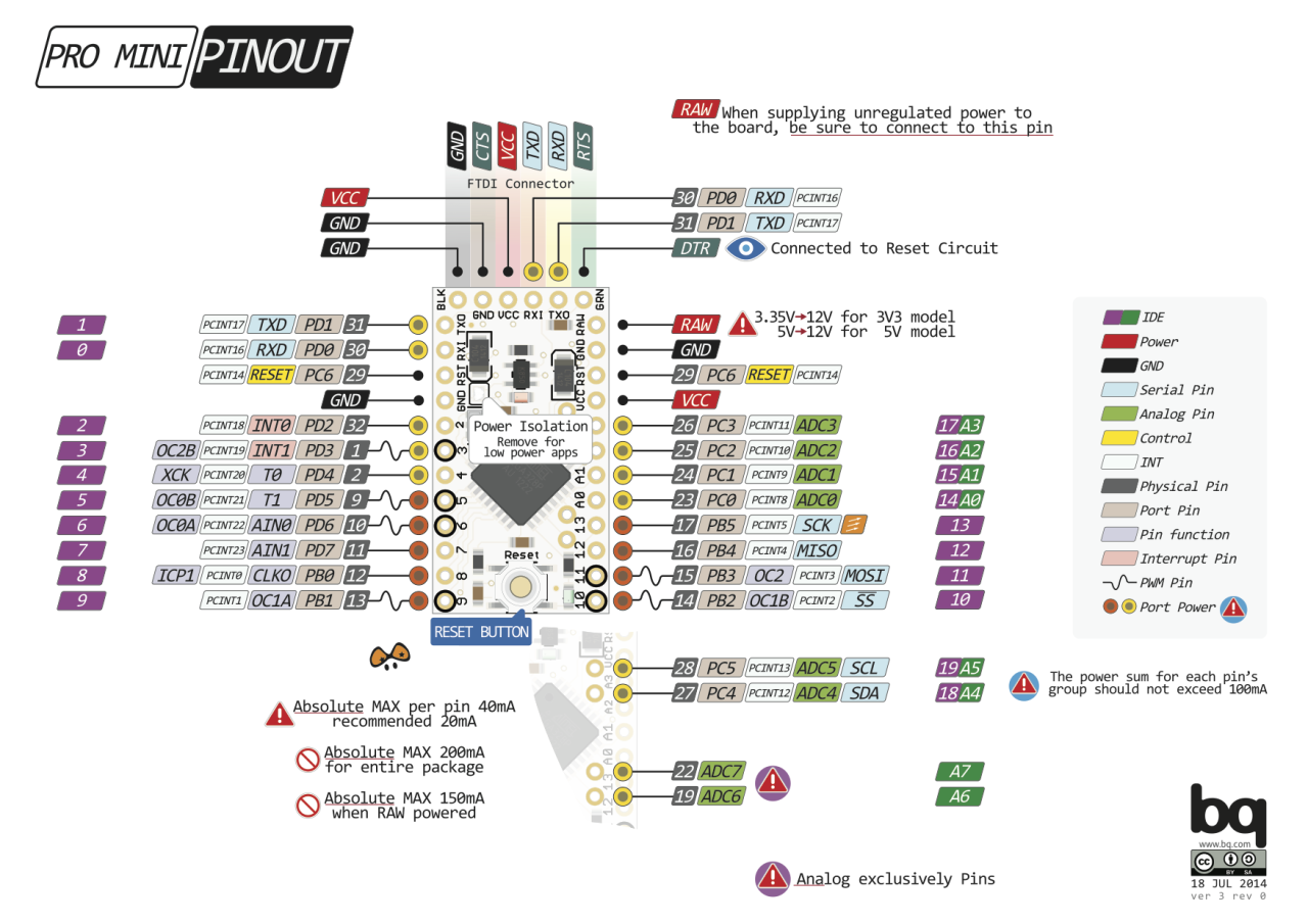
Pin definition
PORT mapping
- PORTD maps to Arduino digital pins 0 to 7
- DDRD - The Port D Data Direction Register - read/write
- PORTD - The Port D Data Register - read/write
- PIND - The Port D Input Pins Register - read only
- PORTB maps to Arduino digital pins 8 to 13 The two high bits (6 & 7) map to the crystal pins and are not usable
- DDRB - The Port B Data Direction Register - read/write
- PORTB - The Port B Data Register - read/write
- PINB - The Port B Input Pins Register - read only
- PORTC maps to Arduino analog pins 0 to 5. Pins 6 & 7 are only accessible on the Arduino Mini
- DDRC - The Port C Data Direction Register - read/write
- PORTC - The Port C Data Register - read/write
- PINC - The Port C Input Pins Register - read only
LED blinking example
- Make sure your makefile have defined F_CPU for clock
#ifndef F_CPU
#define F_CPU 16000000UL // 16 MHz clock speed
#endif

#include <avr/io.h>
#include <util/delay.h>

int main(void)
{
  DDRC = 0xFF; //Nakes PORTC as Output
  while(1) //infinite loop
  {
    PORTC = 0xFF; //Turns ON All LEDs
    _delay_ms(1000); //1 second delay
    PORTC= 0x00; //Turns OFF All LEDs
    _delay_ms(1000); //1 second delay
  }
}
Program
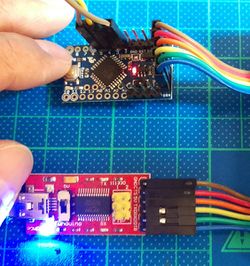
- The connections to make from the FTDI FT232RL and the Pro Mini are:
FTDI232    Arduino_mini
GND    -->   GND

CTS    -->   GND

VCC    -->   VCC (5V for Ardunio Pro Mini 328 - DEV-1113)

TXD    -->   RXD

RXD    -->   TXD

DTR    -->   DTR
- Program command
- make program ...or
- sudo avrdude -q -c arduino -P /dev/ttyUSB2 -b 57600 -p atmega328p -U flash:w:led.hex
avrdude: AVR device initialized and ready to accept instructions
avrdude: Device signature = 0x1e950f
avrdude: NOTE: FLASH memory has been specified, an erase cycle will be performed
         To disable this feature, specify the -D option.
avrdude: erasing chip
avrdude: reading input file "led.hex"
avrdude: input file led.hex auto detected as Intel Hex
avrdude: writing flash (146 bytes):
avrdude: 146 bytes of flash written
avrdude: verifying flash memory against led.hex:
avrdude: load data flash data from input file led.hex:
avrdude: input file led.hex auto detected as Intel Hex
avrdude: input file led.hex contains 146 bytes
avrdude: reading on-chip flash data:
avrdude: verifying ...
avrdude: 146 bytes of flash verified

avrdude: safemode: Fuses OK

avrdude done.  Thank you.

