"Teensy 4.0" 修訂間的差異
(→Memory Map) |
(→Memory Map) |
||
| 行 30: | 行 30: | ||
== Memory Map == | == Memory Map == | ||
| − | Teensy 4.0 has 1 Mbyte of RAM and 2 Mbyte of Flash memory. The RAM is divided into 2 physically separate banks. | + | * Teensy 4.0 has 1 Mbyte of RAM and 2 Mbyte of Flash memory. The RAM is divided into 2 physically separate banks. |
[[File:Teensy4_memory.png|Teensy 4.0 Memory Layout]] | [[File:Teensy4_memory.png|Teensy 4.0 Memory Layout]] | ||
於 2020年7月3日 (五) 10:10 的修訂
目錄
Technical Specifications
- ARM Cortex-M7 at 600 MHz
- 1024K RAM (512K is tightly coupled)
- 2048K Flash (64K reserved for recovery & EEPROM emulation)
- 2 USB ports, both 480 MBit/sec
- 3 CAN Bus (1 with CAN FD)
- 2 I2S Digital Audio
- 1 S/PDIF Digital Audio
- 1 SDIO (4 bit) native SD
- 3 SPI, all with 16 word FIFO
- 3 I2C, all with 4 byte FIFO
- 7 Serial, all with 4 byte FIFO
- 32 general purpose DMA channels
- 31 PWM pins
- 40 digital pins, all interrrupt capable
- 14 analog pins, 2 ADCs on chip
- Cryptographic Acceleration
- Random Number Generator
- RTC for date/time
- Programmable FlexIO
- Pixel Processing Pipeline
- Peripheral cross triggering
- Power On/Off management
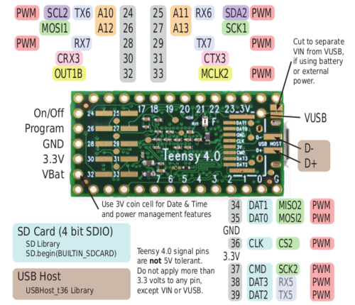
PIN assignment
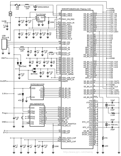
Schematic
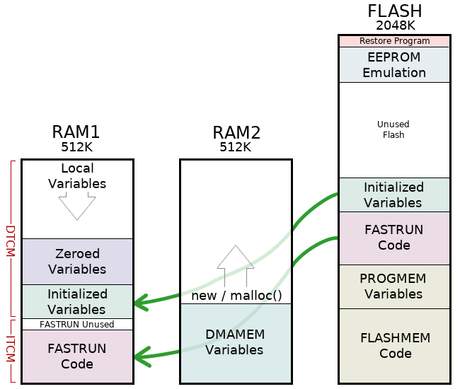
Memory Map
- Teensy 4.0 has 1 Mbyte of RAM and 2 Mbyte of Flash memory. The RAM is divided into 2 physically separate banks.
Teensyduino IDE installation
- Download & Extract Arduino
- Install udev Rules
- The udev rule file gives non-root users permission to use the Teensy devices (serial, HID, etc). More Linux tips below.
sudo cp 49-teensy.rules /etc/udev/rules.d/
PlatformIO
- Install VSCode(Visual Studio Code)
- Install PlatformIO from extensions
MCUXpresso IDE
MCUXpresso Config Tools
MCUXpresso SDK
NXP SDK
export ARMGCC_DIR=$TOOLCHAIN_PATH
cd SDK_2.7.0_EVK-MIMXRT1060/boards/evkmimxrt1060/driver_examples/gpio/led_output/armgcc
chmod 777 build_all.sh
./build_all.sh
arm-none-eabi-objcopy  -O ihex flexspi_nor_release/igpio_led_output.elf flexspi_nor_release/igpio_led_output.hex
teensy_loader_cli -v -w --mcu=imxrt1062 flexspi_nor_release/igpio_led_output.hex
- For led_output example, need to modify gpio mapping in board.h (refer to schematic)
/*! @brief The USER_LED used for board */
#define LOGIC_LED_ON (0U)
#define LOGIC_LED_OFF (1U)
#ifndef BOARD_USER_LED_GPIO
#define BOARD_USER_LED_GPIO GPIO2  <----- modify
#endif
#ifndef BOARD_USER_LED_GPIO_PIN
#define BOARD_USER_LED_GPIO_PIN (3U)  <----- modify
#endif
Upload binary standalone
- teensy_loader_cli -mmcu=imxrt1062 -w evkmimxrt1060_freertos_hello_teensy.hex -v
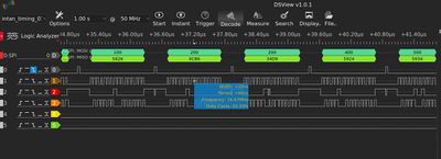
SPI Timing
- CS_OFF around 40 ns
- SPI CLK in 16M
- Sampling rate evaluation
- CS_ON+CS_OFF around 1.46 us
- For 32 Ch in 16M SPI_CLK, the sampling rate for each channel would be:
- (1000000/1.46*32)/1000=21.4KS
SDIO 4 bit
- Format SD before running
- Change pin define in code
- SD.begin(BUILTIN_SDCARD)
/*
  SD card datalogger

 This example shows how to log data from three analog sensors
 to an SD card using the SD library.

 The circuit:
 * analog sensors on analog ins 0, 1, and 2
 * SD card attached to SPI bus as follows:
 ** MOSI - pin 11, pin 7 on Teensy with audio board
 ** MISO - pin 12
 ** CLK - pin 13, pin 14 on Teensy with audio board
 ** CS - pin 4,  pin 10 on Teensy with audio board

 created  24 Nov 2010
 modified 9 Apr 2012
 by Tom Igoe

 This example code is in the public domain.

 */

#include <SD.h>
#include <SPI.h>

// On the Ethernet Shield, CS is pin 4. Note that even if it's not
// used as the CS pin, the hardware CS pin (10 on most Arduino boards,
// 53 on the Mega) must be left as an output or the SD library
// functions will not work.

// change this to match your SD shield or module;
// Arduino Ethernet shield: pin 4
// Adafruit SD shields and modules: pin 10
// Sparkfun SD shield: pin 8
// Teensy audio board: pin 10
// Teensy 3.5 & 3.6 on-board: BUILTIN_SDCARD
// Wiz820+SD board: pin 4
// Teensy 2.0: pin 0
// Teensy++ 2.0: pin 20
//const int chipSelect = 36;

void setup()
{
  //UNCOMMENT THESE TWO LINES FOR TEENSY AUDIO BOARD:
  //SPI.setMOSI(37);  // Audio shield has MOSI on pin 7
  //SPI.setSCK(36);  // Audio shield has SCK on pin 14

 // Open serial communications and wait for port to open:
  Serial.begin(9600);
   while (!Serial) {
    ; // wait for serial port to connect. Needed for Leonardo only
  }


  Serial.print("Initializing SD card...");

  // see if the card is present and can be initialized:
  if (!SD.begin(BUILTIN_SDCARD)) {
    Serial.println("Card failed, or not present");
    // don't do anything more:
    return;
  }
  Serial.println("card initialized.");
}

void loop()
{
  // make a string for assembling the data to log:
  String dataString = "";

  // read three sensors and append to the string:
  for (int analogPin = 0; analogPin < 3; analogPin++) {
    int sensor = analogRead(analogPin);
    dataString += String(sensor);
    if (analogPin < 2) {
      dataString += ",";
    }
  }

  // open the file. note that only one file can be open at a time,
  // so you have to close this one before opening another.
  File dataFile = SD.open("datalog.txt", FILE_WRITE);

  // if the file is available, write to it:
  if (dataFile) {
    dataFile.println(dataString);
    dataFile.close();
    // print to the serial port too:
    Serial.println(dataString);
  }
  // if the file isn't open, pop up an error:
  else {
    Serial.println("error opening datalog.txt");
  }
}


