"Teensy 4.0" 修訂間的差異
(→Schematic) |
(→Schematic) |
||
| 行 36: | 行 36: | ||
== Schematic == | == Schematic == | ||
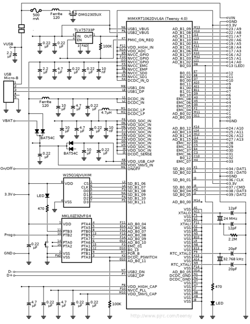
[[File:Schematic40.png|500px|Teensy 4.0 shematic]] | [[File:Schematic40.png|500px|Teensy 4.0 shematic]] | ||
| − | [[File:Schematic41.png|500px|Teensy 4. | + | |
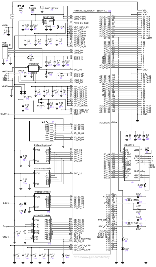
| + | [[File:Schematic41.png|500px|Teensy 4.1 shematic]] | ||
== Memory Map == | == Memory Map == | ||
於 2021年1月5日 (二) 15:35 的修訂
目錄
Technical Specifications
- ARM Cortex-M7 at 600 MHz
- 1024K RAM (512K is tightly coupled)
- 2048K Flash (64K reserved for recovery & EEPROM emulation)
- 2 USB ports, both 480 MBit/sec
- 3 CAN Bus (1 with CAN FD)
- 2 I2S Digital Audio
- 1 S/PDIF Digital Audio
- 1 SDIO (4 bit) native SD
- 3 SPI, all with 16 word FIFO
- 3 I2C, all with 4 byte FIFO
- 7 Serial, all with 4 byte FIFO
- 32 general purpose DMA channels
- 31 PWM pins
- 40 digital pins, all interrrupt capable
- 14 analog pins, 2 ADCs on chip
- Cryptographic Acceleration
- Random Number Generator
- RTC for date/time
- Programmable FlexIO
- Pixel Processing Pipeline
- Peripheral cross triggering
- Power On/Off management
- FPU support
Teensy 4.0's Cortex-M7 processor includes a floating point unit (FPU) which supports both 64 bit "double" and 32 bit "float".
With M4's FPU on Teensy 3.5 & 36, and also Atmel SAMD51 chips, only 32 bit float is hardware accelerated.
Any use of double, double functions like log(), sin(), cos() means slow software implemented math.
Teensy 4.0 executes all of these with FPU hardware.
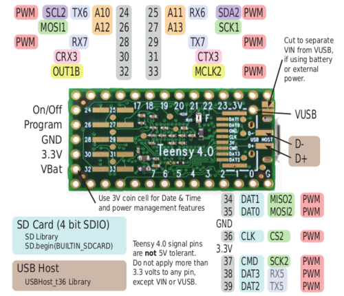
PIN assignment
Schematic
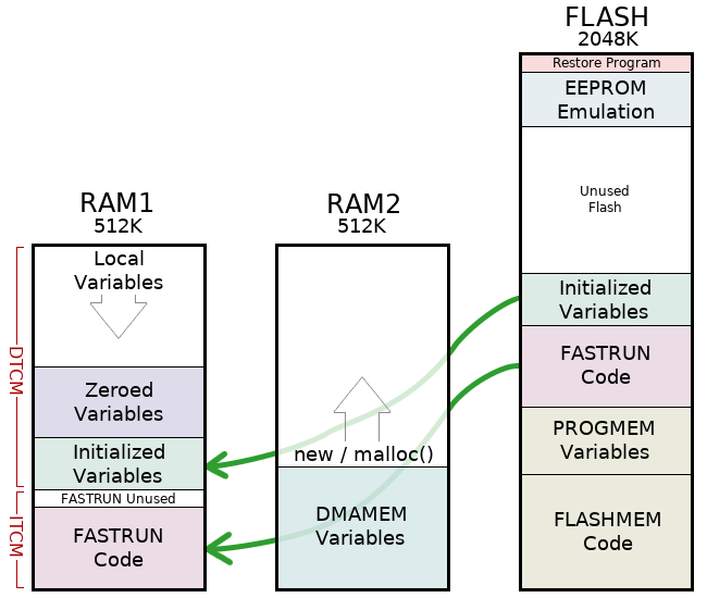
Memory Map
- Teensy 4.0 has 1 Mbyte of RAM and 2 Mbyte of Flash memory. The RAM is divided into 2 physically separate banks.
Teensyduino IDE installation
- Download & Extract Arduino
- Install udev Rules
- The udev rule file gives non-root users permission to use the Teensy devices (serial, HID, etc). More Linux tips below.
sudo cp 49-teensy.rules /etc/udev/rules.d/
PlatformIO
- Install VSCode(Visual Studio Code)
- Install PlatformIO from extensions
MCUXpresso IDE
MCUXpresso Config Tools
MCUXpresso SDK
NXP SDK
export ARMGCC_DIR=$TOOLCHAIN_PATH
cd SDK_2.7.0_EVK-MIMXRT1060/boards/evkmimxrt1060/driver_examples/gpio/led_output/armgcc
chmod 777 build_all.sh
./build_all.sh
arm-none-eabi-objcopy  -O ihex flexspi_nor_release/igpio_led_output.elf flexspi_nor_release/igpio_led_output.hex
teensy_loader_cli -v -w --mcu=imxrt1062 flexspi_nor_release/igpio_led_output.hex
- For led_output example, need to modify gpio mapping in board.h (refer to schematic)
/*! @brief The USER_LED used for board */
#define LOGIC_LED_ON (0U)
#define LOGIC_LED_OFF (1U)
#ifndef BOARD_USER_LED_GPIO
#define BOARD_USER_LED_GPIO GPIO2  <----- modify
#endif
#ifndef BOARD_USER_LED_GPIO_PIN
#define BOARD_USER_LED_GPIO_PIN (3U)  <----- modify
#endif
Upload binary standalone
- teensy_loader_cli -mmcu=imxrt1062 -w evkmimxrt1060_freertos_hello_teensy.hex -v
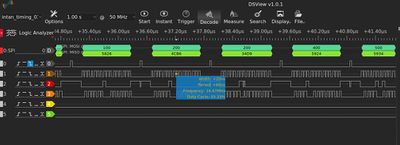
SPI Timing
- CS_OFF around 40 ns
- SPI CLK in 16M
- Sampling rate evaluation
- CS_ON+CS_OFF around 1.46 us
- For 32 Ch in 16M SPI_CLK, the sampling rate for each channel would be:
- (1000000/1.46*32)/1000=21.4KS
SDIO 4 bit
- Format SD before running
- Change pin define in code
- SD.begin(BUILTIN_SDCARD)
/*
  SD card datalogger

 This example shows how to log data from three analog sensors
 to an SD card using the SD library.

 The circuit:
 * analog sensors on analog ins 0, 1, and 2
 * SD card attached to SPI bus as follows:
 ** MOSI - pin 11, pin 7 on Teensy with audio board
 ** MISO - pin 12
 ** CLK - pin 13, pin 14 on Teensy with audio board
 ** CS - pin 4,  pin 10 on Teensy with audio board

 created  24 Nov 2010
 modified 9 Apr 2012
 by Tom Igoe

 This example code is in the public domain.

 */

#include <SD.h>
#include <SPI.h>

// On the Ethernet Shield, CS is pin 4. Note that even if it's not
// used as the CS pin, the hardware CS pin (10 on most Arduino boards,
// 53 on the Mega) must be left as an output or the SD library
// functions will not work.

// change this to match your SD shield or module;
// Arduino Ethernet shield: pin 4
// Adafruit SD shields and modules: pin 10
// Sparkfun SD shield: pin 8
// Teensy audio board: pin 10
// Teensy 3.5 & 3.6 on-board: BUILTIN_SDCARD
// Wiz820+SD board: pin 4
// Teensy 2.0: pin 0
// Teensy++ 2.0: pin 20
//const int chipSelect = 36;

void setup()
{
  //UNCOMMENT THESE TWO LINES FOR TEENSY AUDIO BOARD:
  //SPI.setMOSI(37);  // Audio shield has MOSI on pin 7
  //SPI.setSCK(36);  // Audio shield has SCK on pin 14

 // Open serial communications and wait for port to open:
  Serial.begin(9600);
   while (!Serial) {
    ; // wait for serial port to connect. Needed for Leonardo only
  }


  Serial.print("Initializing SD card...");

  // see if the card is present and can be initialized:
  if (!SD.begin(BUILTIN_SDCARD)) {
    Serial.println("Card failed, or not present");
    // don't do anything more:
    return;
  }
  Serial.println("card initialized.");
}

void loop()
{
  // make a string for assembling the data to log:
  String dataString = "";

  // read three sensors and append to the string:
  for (int analogPin = 0; analogPin < 3; analogPin++) {
    int sensor = analogRead(analogPin);
    dataString += String(sensor);
    if (analogPin < 2) {
      dataString += ",";
    }
  }

  // open the file. note that only one file can be open at a time,
  // so you have to close this one before opening another.
  File dataFile = SD.open("datalog.txt", FILE_WRITE);

  // if the file is available, write to it:
  if (dataFile) {
    dataFile.println(dataString);
    dataFile.close();
    // print to the serial port too:
    Serial.println(dataString);
  }
  // if the file isn't open, pop up an error:
  else {
    Serial.println("error opening datalog.txt");
  }
}

